https://docs.google.com/document/d/1aWb-DIHXf-nye1iGfNu1d70OZDlTlwzB7tDg2tbesk8/edit?usp=sharing
Sunday, May 7, 2017
Lab Report
I was able to finish the lab report. The lab report is a good summary for what I have done for last few months. If you want to see my analysis and more detailed outline of what I did, I recommend checking it out:
Tuesday, May 2, 2017
Weekly wrap up #11-12: Conculsion
I was able to finish my testing for all modification. Unfortunately the the ducted props did not work.
It was not able to sustain its own weight as it weigh 2 times the original weight. So for the endurance trials were all null. However for the thrust trials, to test if the ducted prop actually worked, I got a reading of 2.7 N. When I tested it without the ducted prop, I got a reading of 4 N.
That means the Ducted Prop did not work. Some theories behind it not working:
1. Too heavy (thinner walls and smaller)
2. Needs to be precise between the blade and the Duct
3. curvature to increase aerodynamics
The finish trials of the Ducted Props conclude my experimental phase. I am currently creating a presentation and a lab report that will detail my full analysis and experience with this project. I will update my blog with the lab report.
 |
| Quadcopter w/ Ducted Prop |
 |
| Thrust test w/out Ducts |
 |
| Thrust test w/ Ducts |
That means the Ducted Prop did not work. Some theories behind it not working:
1. Too heavy (thinner walls and smaller)
2. Needs to be precise between the blade and the Duct
3. curvature to increase aerodynamics
The finish trials of the Ducted Props conclude my experimental phase. I am currently creating a presentation and a lab report that will detail my full analysis and experience with this project. I will update my blog with the lab report.
Tuesday, April 25, 2017
Weekly wrap up #9-11: data
Sorry for the lack of post for the last few weeks. Due to experiment testing, work, and preparations to head to Kentucky for the Vex World Championships, my posting have been delayed. However as my project is almost coming to a end, I have tried my best to fulfill the original question of my project: increasing endurance of the quadcopter.
As far for testing procedures I followed the first one which was the PVC setup and the timing of how long the quadcopter will last (as depicted with the picture).
 |
| 2 prop |
 |
| 3 prop |
 |
| 4 prop |
This setup allowed me to to control the quadcopter through my computer and ensure each trial has an equal amp usage. I did the same setup for the the extended arm experiment .
But I did a trial where I didn't extend arms rather incorporate weight to test if the weight of the arms had anything to do with the endurance.
With the short amount of time I have I could not follow the flight test procedures. The time to be able to learn how to fly the quadcopter and tune the quadcopter to be able to hover without swaying will be at least another 3 weeks.
This is what I have for data:

currently I don't have data for ducted prop because I am still waiting on materials to be shipped for me to undergo its construction.
What this data is saying so far the as we increase prop number the endurance goes down. It seems like even though thrust is increasing the flight time is decreasing, I feel there might be a negative correlation between thrust and endurance. However my findings will be confirmed once I start the ducted prop test.
In terms of the extend arm prop it seems the endurance is the same for the 2 prop. The theory behind this was that the extended arms was suppose to to decrease vibrations that would happened during the flight. The extended arms allow increase amount of stability however comes with the cost of the extra weight. It seems both the negative and positive aspects are working here. The stability of the quadcopter allows an small increase of flight time however the extra weight seems to decrease it (we know its a the weight problem because of the "weight from extended arm test").
Once I finish the ducted prop test I will update my blog and go forth with my conclusion.
 |
| Extended arms |
With the short amount of time I have I could not follow the flight test procedures. The time to be able to learn how to fly the quadcopter and tune the quadcopter to be able to hover without swaying will be at least another 3 weeks.
This is what I have for data:
currently I don't have data for ducted prop because I am still waiting on materials to be shipped for me to undergo its construction.
What this data is saying so far the as we increase prop number the endurance goes down. It seems like even though thrust is increasing the flight time is decreasing, I feel there might be a negative correlation between thrust and endurance. However my findings will be confirmed once I start the ducted prop test.
In terms of the extend arm prop it seems the endurance is the same for the 2 prop. The theory behind this was that the extended arms was suppose to to decrease vibrations that would happened during the flight. The extended arms allow increase amount of stability however comes with the cost of the extra weight. It seems both the negative and positive aspects are working here. The stability of the quadcopter allows an small increase of flight time however the extra weight seems to decrease it (we know its a the weight problem because of the "weight from extended arm test").
Once I finish the ducted prop test I will update my blog and go forth with my conclusion.
Friday, April 7, 2017
Weekly wrap up #6-8: Testing
Hi for the last few weeks I have been setting up my testing procedures and plans for modification. The current testing procedures call for the following:
Endurance test:
1. Build the testing apparatus that will allow indoor flying procedures
2. Attach quadcopter to the apparatus with a string and allow it to fly
3. Record time for how long it lasts
4. Repeat trial another 4 times
5. Proceed with the next modification and repeat step 2 - 4
6. Proceed with the next test
The endurance test will allow me to analyze if the modifications affect the endurance of the quadcopter at its simple state of hovering. Hovering will eliminate the drag force during foward flight and allow a easier indoor testing. The indoor conditions eliminate the environment as a factor as well.
Thrust test (Work in progress):
Currently I don't have really have any testing procedures with the thrust test. However the plan is to attach the string that is connected to the quadcopter onto the scale and see how much it can lift.The thrust test will allow me to analyze if there is any correlation with the modifications to thrust, and if thrust directly correlates with endurance.
Flight test (Work in progress)
If I have time left in this project, I will bring the quadcopter outdoors and fly it around till the battery dies. This will simulate a realistic view and usage of the quadcopter as it will factor the environment conditions that will interact with the quadcopter during recreational flight the user will intend to do when they use a quadcopter.
So with the testing procedures laid out I was ready to start testing. Originally my testing apparatus involved a slab of wood and a string attached to the quadcopter.
 |
| Me and with the original testing apparatus |
However that didn't end well because the quadcopter was unpredictable and could of gone anywhere in the room.
 |
| Quadcopter on landing platform |
 |
| Quadcopter during air mode |
Thursday, March 16, 2017
Weekly wrap up #4, 5 and 6 1/2
For week 5 and 6 1/2, I was able to finally build the quadcopter. However I had huge complications getting the initial flight. The problem was that the quadcopter could not take off. Some initial diagnostics were that I thought the quadcopter was too heavy for the motors to lift. However after some testing I realize it was not weight of the quadcopter that was holding it down, but the fact that the motors were not accelerating fast enough to produce the thrust. The only thing that directly correlates to motor acceleration was the battery. The specs of the battery at the time were: 11.1 volts, discharge rate of 22C. and 2250 mAh. Thus I got a battery with a discharge of 45C constantly and a burst discharge of 90C so the motors can intake more charge. The battery also has a mAh of 1300 but that it doesn't affect the acceleration of the motors.
This increase intake of charge allows faster acceleration of the motors which allowed more thrust. The end result was that the quadcopter flew.
But the quadcopter kept flipping over whenever it tried to take off. I wasn't sure if it was a hardware problem (the motors are damaged) or a software problem. So how I tested this was that I switch the different inputs of the wires of the motor ESCs that connect to the flight controller to see if the motors are damaged. If I got different outputs from the initial outputs I got from the program that means the motors are damaged. I got same output, which means it is a software coding problem.So I looked into the quadcopter software. I mainly use two different ones Clean flight and base flight.
I realized when I used the receiver (controller) the motor throttle speed was different among all 4 motors.


I knew this was the source of the flipping over. After intensive research the trim (the sliding buttons) was responsible for the the unequal motor distribution.

The reason why is that the quadcopter was not at is neutral state, it was thinking it needed to compensate for the yaw, pitch, and roll variables thus accelerating and decelerating the motors thinking that was the stable state. I adjust all the yaw, roll, and pitch variables to the 1500 RC input (1500 is the RC input center value). After fixing the receiver, the qaudcopter flew.
However it failed the integrity test as it did not survive the numerous fail landings during our first flight (Flying a quadcopter is not easy at all).

I fixed many of the build flaws I had initially with the quadcopter:
1. Fixed the soldering job of the bullet connectors, as well the soldering job of the power distribution board.
2. Took all the tape of that secured the wires and exchange it with zip ties.
3. Tighten all the screws
4. inserted more screws
5 installed self stabilization program

I try to fly it again, but it flipped during take off and actually broke one of our propellers. I brought it back to test it. After a thorough investigation and crying, I found that it was auto stabilizing during the take off causing unequal distribution of motor output (motor 3 was accelerating while motor 2 decelerate causing to flip). This time it was not the trim problem but one the modes I added after the rebuild. When I flip the switch to the highest mode (3 modes) it would switch on the self stabilization mode as it was at the medium switch mode.
So at start the quad copter was acting it needed to stabilized it self. Should I also mention I had to switch to base flight because the clean flight software on my 2012 mac failed to register my receiver.
After checking it everything works I yet to test it yet. However it seems like the motors outputs are equally distribute which is good.
What I hope to accomplish for the other half of week 6 1/2 and week 7 (Spring break), is to start testing number of propellers. I have about a month left and my plan is to incorporate longer arm lengths and ducted propellers. I am in a time crunch right now. I didn't expect the quadcopter build to be so difficult.
What I learned:
1. Murphy's law is a pain in the butt
2. I enjoy the stress of everything going wrong because that's how engineering works. We build if it doesn't work, we build again. Welcome to the world of engineering.

This increase intake of charge allows faster acceleration of the motors which allowed more thrust. The end result was that the quadcopter flew.
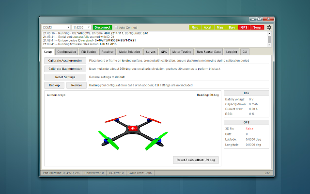
But the quadcopter kept flipping over whenever it tried to take off. I wasn't sure if it was a hardware problem (the motors are damaged) or a software problem. So how I tested this was that I switch the different inputs of the wires of the motor ESCs that connect to the flight controller to see if the motors are damaged. If I got different outputs from the initial outputs I got from the program that means the motors are damaged. I got same output, which means it is a software coding problem.So I looked into the quadcopter software. I mainly use two different ones Clean flight and base flight.
 |
| Clean flight software allows the installation and configuration for quadcopter flight |
 |
| Basically clean flight with a different GUI |
I realized when I used the receiver (controller) the motor throttle speed was different among all 4 motors.
I knew this was the source of the flipping over. After intensive research the trim (the sliding buttons) was responsible for the the unequal motor distribution.
The reason why is that the quadcopter was not at is neutral state, it was thinking it needed to compensate for the yaw, pitch, and roll variables thus accelerating and decelerating the motors thinking that was the stable state. I adjust all the yaw, roll, and pitch variables to the 1500 RC input (1500 is the RC input center value). After fixing the receiver, the qaudcopter flew.
However it failed the integrity test as it did not survive the numerous fail landings during our first flight (Flying a quadcopter is not easy at all).
I fixed many of the build flaws I had initially with the quadcopter:
1. Fixed the soldering job of the bullet connectors, as well the soldering job of the power distribution board.
2. Took all the tape of that secured the wires and exchange it with zip ties.
3. Tighten all the screws
4. inserted more screws
5 installed self stabilization program
 |
| Before |
 |
| After |
 |
| Before |
 |
| After |
I try to fly it again, but it flipped during take off and actually broke one of our propellers. I brought it back to test it. After a thorough investigation and crying, I found that it was auto stabilizing during the take off causing unequal distribution of motor output (motor 3 was accelerating while motor 2 decelerate causing to flip). This time it was not the trim problem but one the modes I added after the rebuild. When I flip the switch to the highest mode (3 modes) it would switch on the self stabilization mode as it was at the medium switch mode.
So at start the quad copter was acting it needed to stabilized it self. Should I also mention I had to switch to base flight because the clean flight software on my 2012 mac failed to register my receiver.
After checking it everything works I yet to test it yet. However it seems like the motors outputs are equally distribute which is good.
What I hope to accomplish for the other half of week 6 1/2 and week 7 (Spring break), is to start testing number of propellers. I have about a month left and my plan is to incorporate longer arm lengths and ducted propellers. I am in a time crunch right now. I didn't expect the quadcopter build to be so difficult.
What I learned:
1. Murphy's law is a pain in the butt
2. I enjoy the stress of everything going wrong because that's how engineering works. We build if it doesn't work, we build again. Welcome to the world of engineering.
Thursday, February 23, 2017
Weekly wrap up #2 and 3
For weeks 3 and 4 has been more concentrated in the building aspect of the project. But those weeks were uttermost disappointing. The goal was to finally create the quadcopter so I can start on the variable manipulation. However I am currently behind schedule because of some unfortunate accidents.
Ideally the wiring of the quadcopter should look like this:

Motors: mechanically rotates the propellers
Electric speed controllers (ESC): Controls the speed of the motors
Receiver: Connects the flight controller to the handheld controller
Flight control: Computer of the quadcopter; has all the sensors to allow the quadcopter to fly
Battery: holds the charge
The reason behind the unfortunate accident was because I plugged a 11.1 V battery into transmitter and flight controller which resulted both micro chips to smoke. This accident hindered the completion of the the control quadcopter. So testing has to be pushed back to a week or two.
So with this in mind, I have only this so far:


Which are just the the electrical speed controller (ESC) wires connected to the motor which are all connected to the power distribution board (the power distribution board just distributes all the current and voltage from the battery, similar to how an outlet works). On the bright side I was able to learn soldering techniques for small micro chip boards like the power distributor board, and the for the short time I had flight controller, the software to calibrate the quadcopter.
All parts lost in the project are currently being replaced and will take two to three days for it to be delivered. The current plan for week 4 is to finally finish the building and test.
Once I get my parts the process of building should be easy and not take as long as it did for me this week. Despite the current drawbacks, I have learned quite a lot and what not to do during the construction of the quadcopter. Most importantly I learned to move on and fix my problems.

Sunday, February 12, 2017
Weekly Wrap Up #1
According to the syllabus this week I am suppose to start building my control quadcopter and start reading the research papers. So far I have read paper Influence of Aerodynamics on Quadrotor Dynamics, and bought the parts for the quadcopter. With the research Mannat and I have conducted separately, we were able to help each other and list down the appropriate the equations that will help with our projects. And just a clarification, Mannat and I are doing separate projects just the same object of manipulation. He is working on how to increase vertical speed of a quadcopter, while I am working on the endurance of the quadcopter. Here are some pictures of the work we have done so far:


The picture above describes the standard thrust equation
This picture depicts the the different dimensions of the quadcopter: pitch, roll, and yaw and the equation to calculate that particular dimension. The the equation in the bottom corner is the equation to calculate vertical speed.
The picture conveys the static thrust equation for the quadcopter. We were able to derive it to prove that in order for the quadcopter to hover it must be equation to its mass x gravity. We also found out that power is portional to thrust, but inversely proportional to diameter. This particular information will help out my research into blade length and thrust.
This picture is similar to the last but we added the equation of the theoretical flight time of my quadcopter with the battery I will be using. The maximum time should be about 5.2 minutes. But with all the environmental factors and inefficiencies of the quadcopter, I am predicting about an actual 3 mins of flight time. The goal is to reach as close to 5.2 minutes.
All of the work and equations we have done so far will be put into a engineering notebook. I plan to post pictures of the notebook in the future. For week 2 I plan to continue my research and build the control quadcopter.
-Adriane Inocencio
Subscribe to:
Posts (Atom)